The Big Gun Project has finally started. The goal is to be able to fire a 15 oz. tin can(bean can) full of concrete, 440 yards. This 'bullet' weighs about 2 pounds. Tests with an earlier gun make me think it is possible without using high pressure. I plan to use 100 psi or less with a 10 foot barrel.
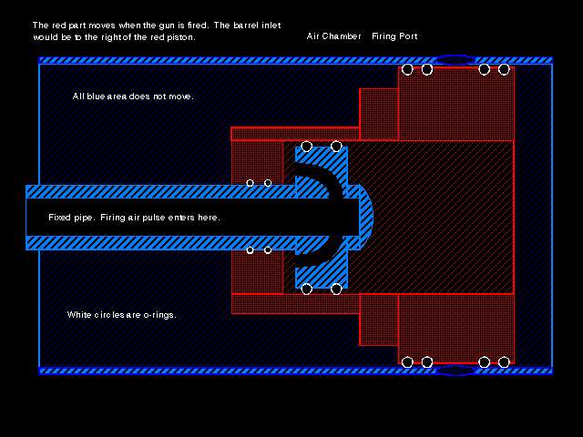
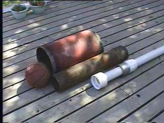
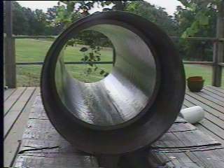
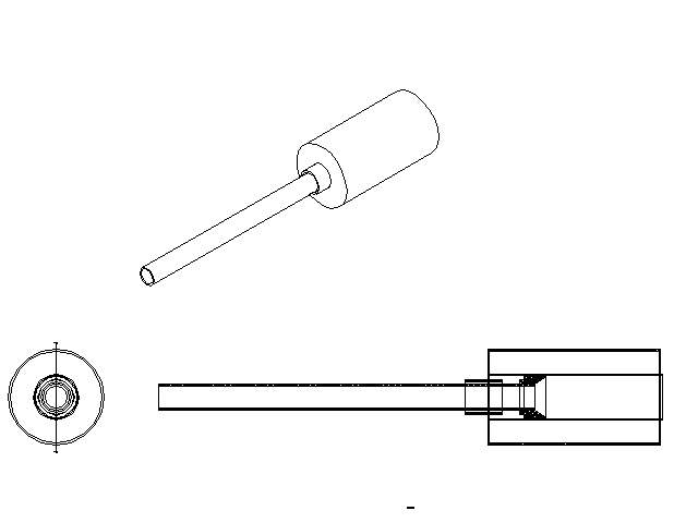
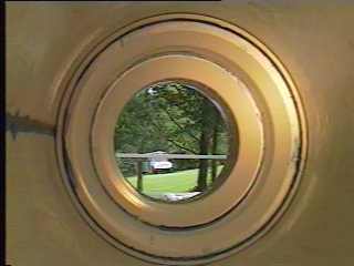
The design is something like a diaphragm type gun. Instead of a diaphragm it uses a sliding valve/piston to valve the air into the barrel. Most guns of this type use the gun's firing pressure to drive the piston back, away from the barrel opening, firing the gun. In the case of this design the piston will be driven by an external air source. One reason for this type design is that the pressure will be valved in from the side of the valve and into a inner chamber. This arrangement needs a different method for moving the valve. The inner chamber will be 6 inches in diameter and funnel down to the 3 inch barrel. My hope is that this funnel effect will increase the air velocity in the barrel. Your bullet will never be able to go faster that the air coming out of the barrel. So, I am designing from the ground up, to improve airflow. The main pressure chamber is 12 inch diameter, 0.25 inch thick steel, gas pipeline. It is about 22 inches long and was free. No trouser legs required here! The inner chamber is where the sliding valve will ride and the funnel area is forward of the valve. This inner chamber is 6 inch diameter, 0.125 inch steel pipe. It will have a PVC lining for the valve to ride in. This will provide a smooth, rustfree surface for the valve's o-rings to seal against. I have tried to make a couple of crude drawing to show the assembly and the valve. The valve, when pulled back, will allow air to rush in from ports in the side of the inner chamber. This is the first part of the gun I will build. If it does not work before being assembled inside the main chamber it will not be too late to try something else. Here are some of my parts. This is the start of the piston/valve, disassembled.
27 Jun 98
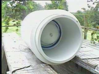
The lining for the inner chamber required a PCV pipe to have a section removed and pressed into the inner chamber. To get a good fit on the joint, the seam must be just right. Here I am using hose clamps and a file to finish the gap. The pipe was squeezed to fit inside the steel inner chamber. After I got what I thought was a good fit, I pushed the liner in. It was a tight fit, but I think I will put some screws in it to secure it to the inner chamber.
30 Jun 98
I have been trying to learn some CAD. Here is my drawing, so far. I also made a PDF file of the drawing that you an zoom in on to see more detail.
2 Jul 98
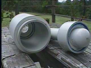
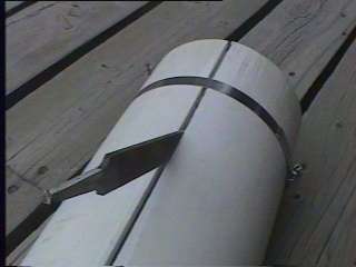
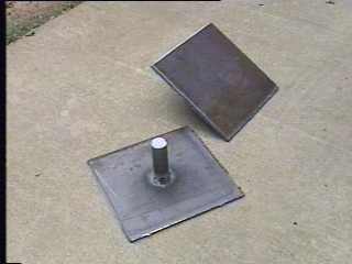
I bought some steel plates(13 inch square 1/4 thick) today to make the endplates with. I work at Baldor, where we make electric motors. I took a couple of shaft scraps and welded them to the plates to chuck them on. A couple of days ago I added an outside layer to the barrel adapter(funnel) and turned it down to fit the inside of the inner chamber liner. Here is a photo of it in place.
3 & 4 Jul 98
Off work for the 4th. I tried to turn the plates and found that they were not very straight. I banged on one with a hammer and got it a little straighter. Then the tack weld broke. I had them welded on straight but the shaft stock (which I had got from the waste bin) was not as square as it appeared. So, I cut a shoulder on the shaft and bored a hole in the plate. This worked a lot better and after several hours I had one plate finished.
I also started working on the ports of the inner chamber. I had to buy a hole saw ($15, ouch!) and was careful to cut with oil to keep it cool so the teeth would not be damaged by heating. There are going to be 12 ports so I drilled 24 1" holes. I cut the material between each part of holes to create a oval port in the inner chamber. When I am finished the liner will go back in and ports will be cut in it also.
8 Jul 98
I got the most of the large PVC parts today to finish the valve, but have some house repairs to do first. I also weighed all the parts I have for the gun. The total weight of the parts is 138 pounds. That means when I get the mount made and the other add-ons the weight will approach 150 pounds.
11 Jul 98
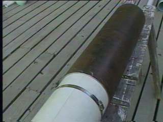
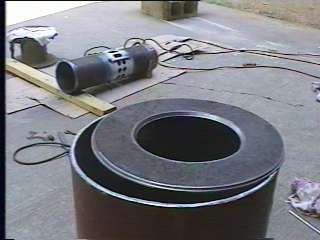
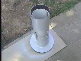
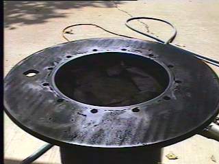
For most of the day I worked on making parts. The endplate for the front end for the gun is now finished. The inner chamber will be centered and welded to this plate on the inside. I found a good way to center it. I have some 0.25 inch square key stock. I marked a circle on the endplate blank the same size as the outside diameter of the inner chamber. Then I welded the key stock to where the ends crossed the circle but most of the key was inside the circle. I then turned, on a lathe, the ends of the keys off until the inner chamber would slip over the keys. This forced centering of the inner chamber. Here is a photo of the front endplate at the bottom of the main chamber. The rear endplate is setting on top of the chamber.
Here are most of the parts. 138 pounds of them!
1.Main chamber 2.Rear endplate 3.Front endplate 4.Inner chamber 5.Piston/valve
6.Funnel 7.Barrel 8.Steel barrel adapter 9.Barrel adapter
I am getting close to starting assembly.
14 Jul 98
Today I took a day of vacation. I welded the steel barrel adapter to the front endplate. Then I welded the front endplate to the inner chamber. I painted the inner chamber to prevent rust inside the gun. The liner for the inner chamber is back in place, after all the welding was done on the front end. Next I will cut the ports into the inner chamber's liner.
18 Jul 98
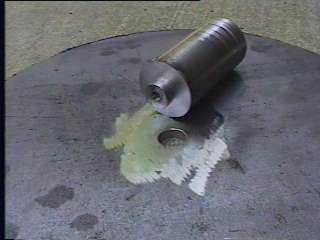
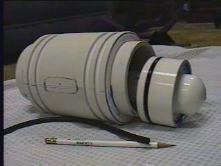
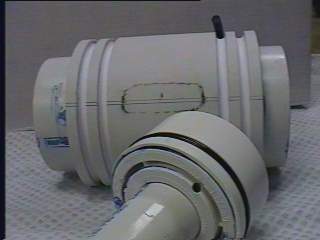
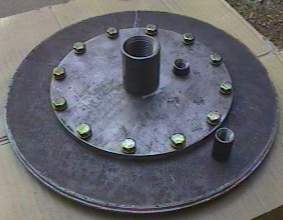
Yesterday and today proved to be good days for the biggun parts production. I was able to get the piston finished (almost).You can see a sketch of one of the inner chamber's ports on the side of the piston, with the o-ring grooves on each side of the port position. The 'head' has ports in it to pass the firing pulse into the piston's working space. In this photo you can see one of the air ports in the 'head'. This part will be fixed to the valve access plate and the piston will move away from it. So, I decided to call it the 'head'(like on a car engine). The valve access plate can be seen sitting on the rear endplate and will be the only access to the inside of the gun. Everything that might need fixed or replaced will have to come out by removing this plate. Inside the bolt circle is a 1 inch coupling. This is for the firing pulse of air to enter. The smaller (1/4 inch) coupling is for putting air in to force the piston back to the sealed position for the next shot. This hole could also be used with a measuring rod to determine if the piston was in the home position before the gun was loaded or charged with air.
27 Jul 98
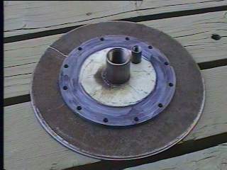
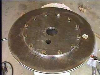
I did a little work Saturday and today(Monday) on the rear endplate and valve access plate. The hole pattern of the valve access plate was transfered to the rear endplate and it was drilled so the holes would all line up. On the back of the rear endplate I welded nuts for the cap screws that hold the valve access plate on. Here is a photo of it with the screws in place and the coupling (1/4") that will be used to pipe the air into the main chamber for power. Also pictured are the two couplings that will be used to fire the valve and return it to sealed position.
I am also working to smooth out the liner in the inner chamber. It is not quite round and has something of a rough finish inside. I made a sanding drum with a handle in the middle of it. With this and a lot of work I think I can get it in shape to where the o-rings will seal okay.
1 Aug 98
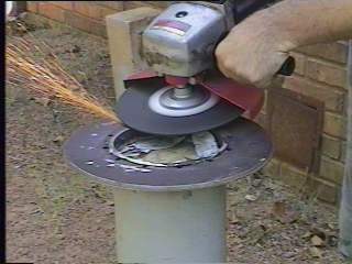
Back to assembly. I welded the rear endplate to the inner chamber. The bolt circle for the valve access plate are almost too close to the weld. Extreme care is required to avoid screwing up the holes in the endplate. After I finished welding I ground the end of the inner chamber flush with the rear endplate. Then I test mounted the valve access plate. This plate does not have to hold air pressure, if I can get the valve I plan to use to work right. If it don't work I can convert it to a diaphragm gun. In this case a seal of some sort will be required on the valve access plate. One(of 12) hole was a little off, because of the welding (I think) and it was fixed with a file. You can see the two holes in the valve access plate plus the one in the rear endplate that will have couplings welded to them. That is the next operation.
11 Aug 98
The testing of the valve/piston went well today. For detailed information on the valve and test, look at this page.
The next major task is final assembly. This is one thing I have been waiting for. It will finally start looking like the final product. My wife (Lisa) thinks it looks like a bomb.
27 Aug 98
I am almost ready to test fire the gun. There is some glue inside that is drying very slowly(trying to fix a leak), so I think I will give it a few more days and work on a gun mount in the mean time. If you want to see the latest photos here they are.
29 Aug 98
Well the glue did not hold. The air is getting behind the inner chamber's liner and making it's way to the barrel attachment area. I tried to soak the area where the air is coming into the area in front of the barrel funnel hoping it would fill the leake channel. It blew out at about 30 psi. I will try to fix this later. For now I will work on the mount for the gun. I want something that can pivot up and down. Plus, be able to swing left and right. I started off with a cradle to set the gun in. From there I will build under it with the pivot assembly. I got the cradle finished today.
5 Sep 98
One more step in the mount for Big Red (biggun's new name). This mount took most of the day and will pivot up and down only.
7 Sep 98
I am still fighting internal leaks. Now the entire void space in front of the 'funnel' is solid polyester resin. Late in the afternoon I test it at 40 psi and it holds. I make about 5 test firings and move the gun down to my brother's house. Here it is set up and ready to go. We fired pork&bean cans full of concrete across the valley toward the next hill.
30 Jan 99
With winter here there is less chance to shoot and finally time to work on that leak. I have it fixed now and after shooting several shots today part of the valve driving assembly broke. The PVC just snapped where it was connected to a steel pipe nipple. Oh will, back to the drawing board. Before it broke I used my chronograph and got some velocities on several shots. A 29 oz can of concrete went 256 feet/sec and a 15 oz can of water was measured at 347 feet/sec. An empty can went 805 feet/sec.
That is all for now.